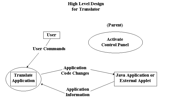
The diagrams that follow describe
the flow of data between processes within the system. The diagram
labeled "Level_0_DFD" shows the context of the system.
There is an Application that contains the control system
within it and a User that by giving its preferences to
the Control Software can alter the characteristics of certain
components within the Application. That Control Software
process is broken down into three sub-processes on the following
diagram. This process of peeling away layers of abstraction is
continued through the remaining diagrams until a point where understanding
of data flow within the system is trivial.

Page 15 |
Document Index |
Page 17 |