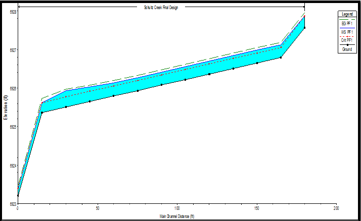
Final Design Recommendation
The final design recommendation is a short restoration with a rock structure. The restoration provides stabilization of the channel without disturbing the grove of trees located in the floodplain above the restoration site.
Vegetative Bank Support
Shown below in Figure 7 is the final design with vegetative assistance using willow transplanting. The green circles represent willow bundles.
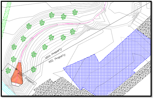
Figure 7 – Recommended design with Vegetative bank support
As shown above, willow bundles shall be transplanted from the existing channel. When using willow bundles for channel support, one must consider the following (Allen, Leech 2008);
- The bundle ends must be below the lowest water surface elevation
- Bundles must be installed at a 45 degree angle downward. Bundles are not to be installed horizontally.
- Bundles are to be placed to the height of above normal flows. Since Schultz creek is a ephemeral stream, normal flow elevation is considered to be at 100 year flood flow elevation
- Use only Willows which have flexible stems, so debris will not collect as the willows mature.
- Willows shall not be placed within 10’ of channel thalweg, due to constricting natural channel geomorphology.
With the assistance of willows in the corridor, one will see a drop in stream velocity during flooding events. Willows assist with channel roughening. Having willows in the corridor decreases stream velocities at high flows and therefore increase hydraulic retention time in the channel. Increasing the hydraulic retention time of the channel provides the following; an increase in groundwater charging, a more consistent steady flow state, and the rejuvenation of the riparian ecology.
Final Design Plan.pdf
Longitudinal Profile.pdf
Rock Structure
Traditional rock-armoring is used for scour protection. Rock armoring shall be installed two feet below the river thalweg. Rock armoring is considered a structure and is deemed permanent. The upstream side of the rock structure must have keyed in boulders. A trench must be excavated and boulders placed with one-quarter exposed. Following the keyed in boulders, smaller rocks are placed down to the landing of the culvert entrance. The culvert entrance shall have a flat zone up to the wing walls. It is recommended that the flat zone have gravel to prevent scour at the bottom of the rock structure.
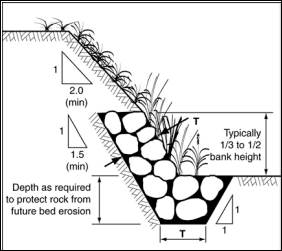
Figure 8 - Traditional Bank Armoring (Catchments & Creeks)
The purpose of this section is to address the ADOT requirements and suggestions regarding the installation and design of rock riprap structures at or near culvert entrances. This may include parameters such as rock size, spacing, distance from culvert, aesthetics, gradient, and more. These regulations are relevant to the Schultz Creek restoration project because the design chosen for implementation consists of a rock riprap structure at the culvert’s entrance. The following bulleted points summarize these ADOT requirements and suggestions:
- Rock riprap must be angular shaped, crushed rock material
- Any portion of the imbedded rock riprap shall not exceed a height of 4 inches above the finished grade
- Rock structures within a drainage area must be installed and maintained to manage at least a 2-year 24 hour storm event
- Immediate corrections/adjustments must be made to the rock structures if they are causing flooding, erosion, or affecting roadway safety
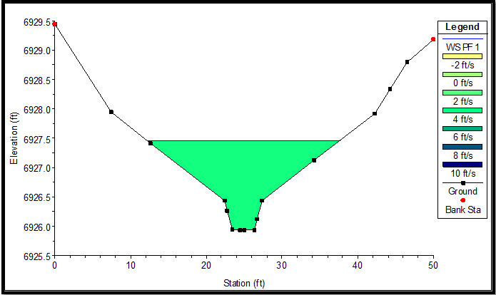
Rock sizing has been established using an average stream velocity of the channel. The max stream velocity was found using a 100 year flood flow. The max velocity was found at the bottom of the rock structure to be 5.5 feet per second. The evaluation of rock sizing was found using Equation 3 (Catchments & Creeks Pty Ltd).
D50 = 0.04 V2 (Equation 3)
Key factors that affect rock sizing are; low turbulence vs high turbulence, angular or rounded rock, poor or well graded rock, specific gravity of rock material, bed slope, factor of safety, and average flow velocity at location of rocks. Assuming angular rocks are used at a specific gravity of 2.6, the rock sizing relationship is reduced to Equation 3. At the channel bed the recommended D50 is 0.4 feet. On the channel side banks a D50 of 0.35 feet is recommended.
Plan and Profile of Rock Structure.pdf
Excess Cut Plan
When the Schultz Creek Restoration Project (SCRP) was in the early stages of design, the original plan was to create a design where the new channel would require about the same amount of cut as the old channel would require fill. If this plan were to work, there would be little excess soil to manage. However, after carefully creating multiple design alternatives, it has been determined that the amount of cut required for all of the design possibilities greatly exceeds the amount of fill required to stabilize the existing channel. Therefore, an excess cut management plan must be put into effect.
There are two possibilities for managing the excess cut on-site. One possibility is to keep it within the ownership of the ACE offices. If this plan of action was taken, the excess soil could be used for other ACE projects that require fill. The other possibility is to give the excess soil away, or even to sell it to help fund the project. The Cinder Lakes Landfill in Flagstaff is in dire need of daily cover material. The landfill operators may be willing to purchase the excess soil for a discounted price, or even pick it up on-site for zero charge. Either of these excess cut management plans would sufficiently deal with the excess soil created on-site.
Final Hydrology
Short Design with Rock Structure HEC-RAS
A.3.a: 3-D Model of Design
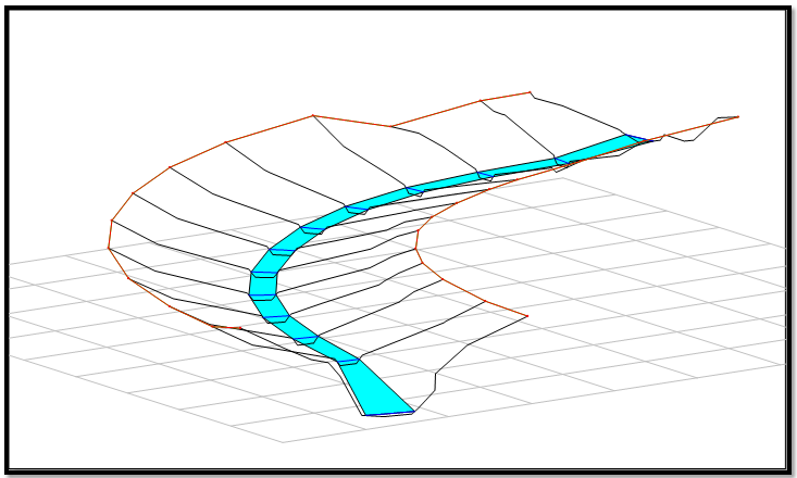
A.3.b: Velocity Profile of Design
A.3.c: Longitudinal Profile of Design
