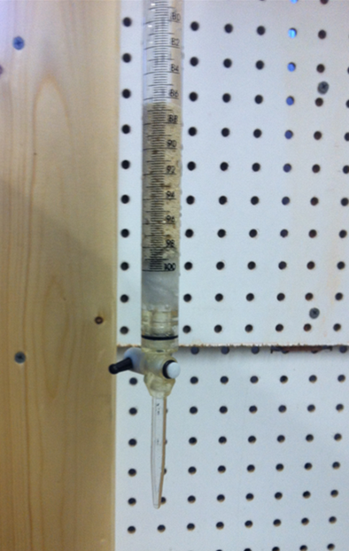
Flow through and a Batch laboratory experiments where constructed. The purpose of the laboratory experiments is to evaluate the resin to ensure the resin behaves as stated in the Engineering Bulletin by Purolite in Appendix 2.
The primary goal of the Flow Through Experiment is to prove that the A520E resin behaves consistently after reaching capacity and being recharged. The secondary goal of the flow through experiment is to develop Freundlich parameters to create a solid phase capacity for the A520E resin. The primary goal of the batch experiments is to create more Freundlich parameters to compare with the parameters generated in the flow through experiment. Purolites guide to laboratory testing of ion exchange and adsorbent resins and was used to create the Flow Through experiment. Due to time constraints the recommended bed volume as stated in the Purolite laboratory testing of ion exchange and adsorbent resins document was reduced from a minimum of 50 mL to 10 mL and the flow rate in bed volumes per hour was increased from 500 ml per hour to 2600 ml per hour. The laboratory protocol for the flow through experiments can be found in Appendix 5.
The primary goal of the Batch Experiments was to develop more Freundlich parameters. The Freundlich parameters from the Flow Through Experiment will be compared to the constants developed in the Batch Experiment. The Batch Experimental Protocol can be found in Appendix 6. The laboratory protocol for the batch experiments was developed using an example problem in the Activated Carbon section Hazardous waste Management by LeGrega and the resin capacity as stated by Purolite in Appendix 2. The example problem is for activated carbon but because activated carbon and ion exchange resin are both adsorbents the example problem was adopted for ion exchange. To ensure the batches reached equilibrium the laboratory protocol was modified to have a longer equilibrium period. The Batch Experiment was done in 2 batches. Batch 1 is called Experiment 2A and batch 2 is called Experiment 2B.
Scale up calculations where generated using 2 methods for redundancy. The goal of the scale up calculations is to optimize a system to the constraints and criteria of the NTS Project in the purpose section of this report.
The first method is a scale up using the final solid phase capacity (qf) generated from Fruendlich Parameters from the Flow Through Experiment. The second method is an application of Appendix 2: The A520 Engineering Bulletin from Purolite which gives guidelines on how to determine how much resin is required for a certain throughput of modeled contaminated groundwater. Both methods where calculated in Microsoft Excel and use the Table of Equivalent mass in Appendix 11. Both methods use a project constrained design period for the scale up calculation of 1 month with a flow rate of 0.2 gallons per minute.The scale up calculations for the first method can be found on page 4 of Appendix 9.
The resulting required bed volume using the solid phase capacity (qf) is 3.54 ft3 of A520E resin. The scale up calculations for the second method can be found in Appendix 10.
The resulting required bed volume using the A520E Documentation is 3.50 ft3 of resin and the resulting concentration out (Cout) using the Figure 2 in Appendix is 3.6 mg/L NO3-N. The resulting concentration out using was selected as 2 mg/L NO3-N. Both methods result in almost the same size required bed volume. A design size of 3.50 ft3 was selected as the design size for the recommended system configuration which is explained in the next section.
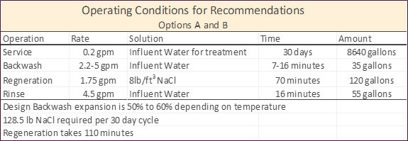
The purpose of the recommended system configuration is to supply some of the primary calculations for the implementation of A520E ion exchange nitrate treatment system as well as a basic parts list and cost estimate. The recommended system configuration uses the scale up calculation inputs and the A520E Engineering Bulletin. The recommended system configuration calculations can be found on page 2 of Appendix 10. 2 recommended system configurations are provided: Option A and Option B. 2 recommended system configurations are provided to give some variance in system shape and operating pressure drop. The operating conditions for the recommendation options are presented in Table 4 below.
Table 4: Operation Conditions for Recommendations
A cost estimate for the system has been made using the parts list presented in Table 5 below. The parts list was developed to create the rough cost estimate. All the costs were found on trustworthy online stores and have been inflated 20%.
Table 5: Basic Parts List for Option A and Option B
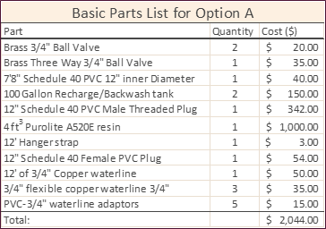
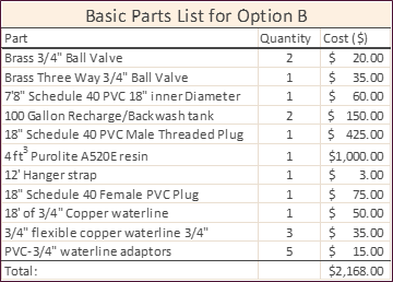
The implementation cost of either option A or B has been estimated to be $2500.00 plus or minus $200.00 assuming a technical rate of $25.00 per hour. An ongoing cost of $168.00 per year for sodium chloride to make the brine recharge solution plus $1150.00 per year in man hours required for the recharge procedure. For further details on the Recommended System Configurations see the Final Report Document in the Project Documents page.
Mixing The Synthetic Water
Flow Through Experimental Column with 10 mL A520E resin bed

